
Celona Antennas and Accessories
Specs for antennas and accessories: omni and sector antennas, GPS timing, PTP grandmaster clocks and splitters.
Download PDF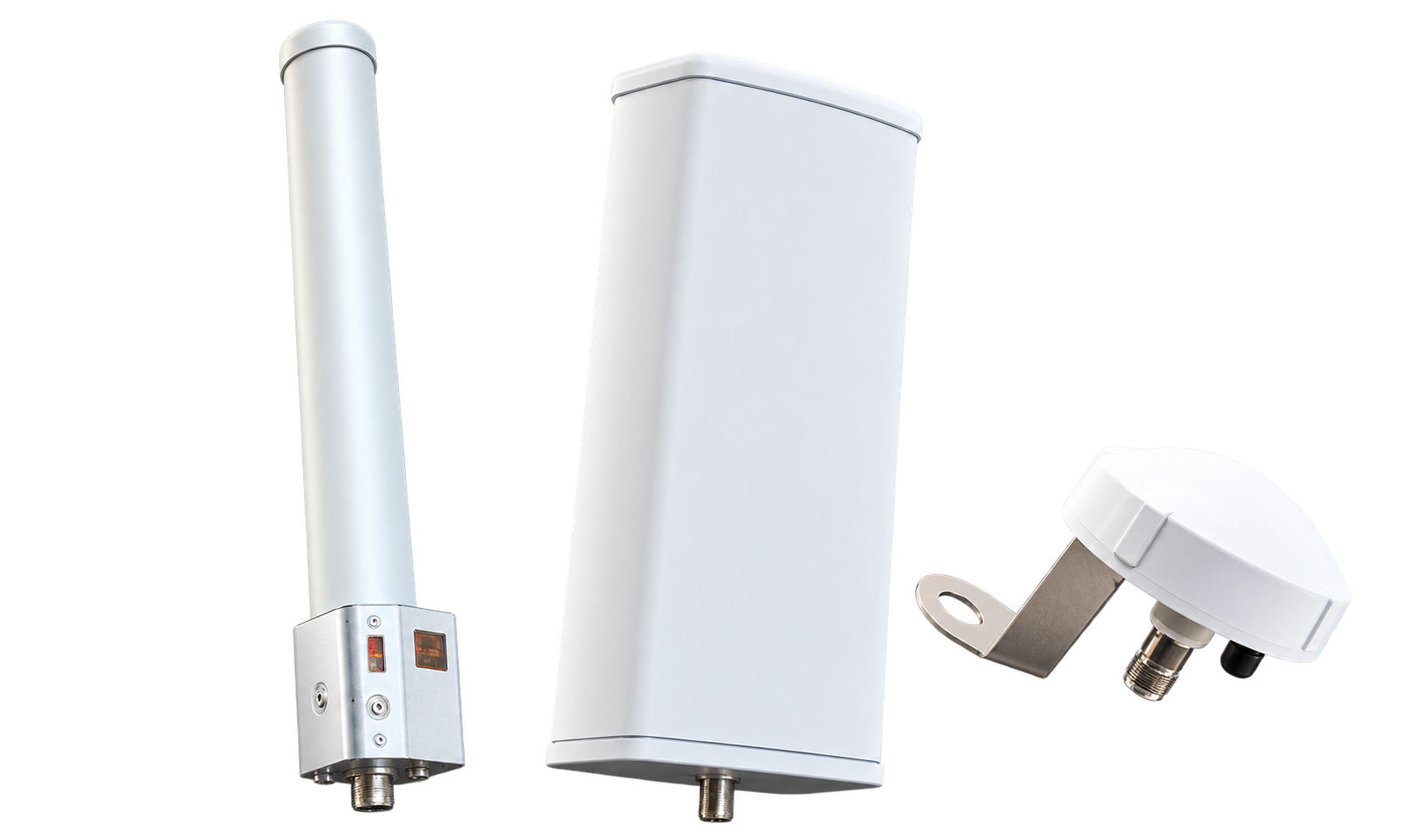
01
CN-ANT-OMNI-KIT
Omni-directional external antenna, 2-port for Celona outdoor access point
Part Number CN-ANT-OMNI-KIT
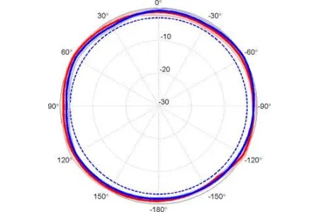
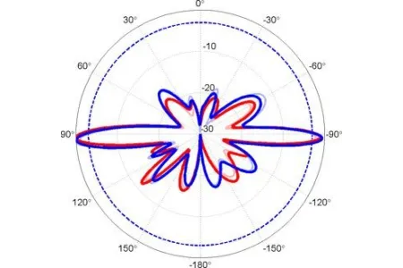
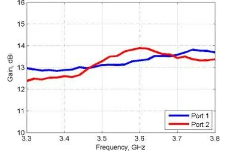
2-port omnidirectional antenna covering 3300–4200 MHz and 4400–5000 MHz with 12–13 dBi gain.
Includes two surge protectors and two LMR400 120” / 3m antenna cables. Two required per Celona outdoor AP.
| Electrical | |
|---|---|
| Frequency range | 3300–4200 / 4400–5000 |
| Polarization | Vertical and Horizontal |
| Gain | 12-13 dBi |
| Elevation 3dB beamwidth | 7 ° |
| Electrical Downtilt | 2 ° |
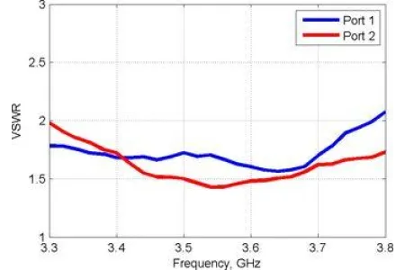
| VSWR | < 2 |
| Cross-pol ratio | > 20 dB |
| V-H port isolation | > 30 dB |
| Input power | 50 W max per port |
| Impedance | 50 Ω |
| Connector Type | Type N Female x 2 |
| Mechanical | |
|---|---|
| Dimensions | Ø125 × 820 mm |
| Weight | 4.5 kg |
| Mounting method | Mast |
| Radome material | PC/ASA |
| Environmental | |
|---|---|
| Temperature range | -40° to +65° C / +150° F |
| Wind speed | 210 km/h / 130 mph |
| UV protection | UV resistant PVC |
| Ingress protection | IP55 rain resistant |
| Lightning protection | DC Ground |
02
CN-ANT-33D-KIT
33-degree sectorized, 2-port external antenna for Celona outdoor access point
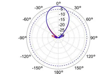
3.5 GHz to 4.2 GHz, 33 Degree Sector Antenna, 18.8 dBi, 2-Port, ±45 Slant
- 4° fixed electrical downtilt
- ProLine sector with stable and high gain
- Interference mitigation with azimuth and elevation side-lobe suppression
- Includes two surge protectors and two LMR400 120” / 3m antenna cables.
- Two required per Celona outdoor AP.
| Electrical Specification | |||
|---|---|---|---|
| Frequency Band | MHz | 3500-3800 | 3800-4200 |
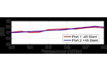
| Gain | dBi | 18.5±0.2 | 18.8±0.3 |
| Polarization | Slant (±45°) | Slant (±45°) | |
| Horizontal HPBW | Degree | 35±1 | 33±1 |
| Horizontal Squint | Degree | ±0.5 | ±0.5 |
| Vertical HPBW | Degree | 8.5±0.5 | 7.8±0.4 |
| Electrical Downtilt | Degree | 4 | 4 |
| Front-to-Back Ratio @ 180°±30° | dB | 35 | 33 |
| Upper Side Lobe Suppression (+20°) | dB | 15 | 15 |
| Cross-polarization Ratio over HPBW | dB | 15 | 13 |
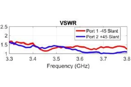
| VSWR | 1.3 typ | 1.5 max | 1.3 typ | 1.5 max | |
| Return Loss | dB | 17 typ | 14 max | 17 typ | 14 max |
| Port-to-Port Isolation | dB | 30 | 25 |
| Max. Input Power per Port | W | 50 | 50 |
| Impedance | Ohms | 50 | 50 |
| Bracket Specification | |
|---|---|
| Material Type | Powder Coated High- Strength Aluminium |
| Mechanical Tilt (Degree) | -1 to +18 (Slot 1) -7 to +11 (Slot 2) |
| Mounting Type | Pipe Mount |
| Mounting pole diameter | 1.9cm - 11.4cm / 0.75" - 4.5" |
| Antenna-to-Pipe Distance | 12.1cm / 4.8" |
| Bracket-to- Bracket Distance | 47cm / 18.5" |
| Mechanical Specifications | |
|---|---|
| RF Connector Type | N-Type Female |
| RF Connector Quantity | 2 |
| RF Connector Position | Bottom of radome |
| Electrical Grounding | RF connector grounded to reflector and bracket |
| Radome Material | UV resistant PVC |
| Reflector Material | Fully-Enclosed Aluminium |
| Ingress Protection | IP55 rain and dust resistant |
| Wind Load, frontal | 135N @ 160km/h | 30lbf @ 100mph |
| Max. Wind Speed | 160km/h | 100mph |
| Temperature Range | -40° to +60° C | -40° to +140° F |
| Sector Dimensions | |
|---|---|
| Length | 58.5cm / 23.0” |
| Width | 17.4cm / 6.9” |
| Height | 7.9cm / 3.1” |
| Net Weight, with brackets | 5.7 kg / 12.5 lb |
| Shipping Dimensions | |
|---|---|
| Length | 102cm / 40” |
| Width | 36cm / 14” |
| Height | 36cm / 14” |
| Net Weight | 7.3 kg / 16 lb |
| Measurement definitions | |
|---|---|
| HPBW | Average and variation of the antenna’s 3dB beamwidth (half power beamwidth) in its horizontal (Azimuth) or vertical (Elevation) pattern. |
| Horizontal Squint | Angle in the antenna’s azimuth pattern in which the maximum gain occurs. Reported is the maximum variation in the frequency band. |
| Electrical Downtilt | Angle in the antenna’s elevation pattern in which the maximum gain occurs. |
| Gain | Antenna’s average gain and variation in each frequency band. |
| Front to Back Ratio @ 180°±30° | Difference between the antenna’s maximum gain and the maximum gain in the antenna’s back lobe over ±30° angles. |
| Upper Side Lobe Suppression | The maximum value for the antenna’s elevation upper side lobes from the main beam to +20°. |
| Cross-polarization Ratio over HPBW (dB) | Maximum difference between the co-polarization and cross-polarization gain across the sector’s HPBW. diameter |

03
CN-ANT-90D-KIT
90-degree sectorized, 2-port external antenna for Celona outdoor access point
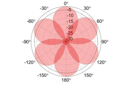
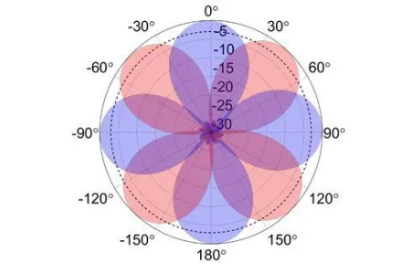
2-port sector antenna, 3300-3800 MHz, 90° HPBW
- High gain and slant dual polarization
- Simultaneously maximize coverage and minimize interference
- Ideal for 3-sector frequency-reuse one with LTE equipment
- Includes two surge protectors and two LMR400 120” / 3m antenna cables.
- Two required per Celona outdoor AP.
| Electrical Specification | |||
|---|---|---|---|
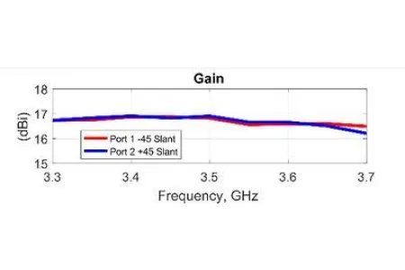
| Frequency Band | MHz | 3300-3550 | 3550-3800 |
| Gain | dBi | 16.7±0.25 | 16.5±0.25 |
| Polarization | Slant (±45°) | Slant (±45°) | |
| Horizontal HPBW | Degree | 85±2 | 90±2 |
| Horizontal Skew | Degree | ±2 | ±3 |
| Vertical HPBW | Degree | 7±0.25 | 6.5±0.25 |
| Electrical Downtilt | Degree | 2 | 3.5 |
| Front-to-Back Ratio @ 180° | dB | 31 | 35 |
| Front-to-Back Ratio @ 180°±30° | dB | 28 | 28 |
| Cross-polarization Ratio at Boresight | dB | 25 | 23 |
| Cross-polarization Ratio over HPBW | dB | 20 | 17 |
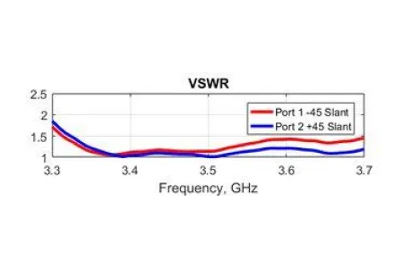
| VSWR | 1.5 typ | 1.7 max | 1.3 typ | 1.5 max | |
| Return Loss | dB | 14 typ | 12 max | 18 typ | 14 max |
| Port-to-Port Isolation | dB | 25 | 30 |
| Max. Input Power per Port | W | 50 | 50 |
| Impedance | Ohms | 50 | 50 |
| Bracket Specification | |
|---|---|
| Material Type | Hot Dipped Galvanized Steel |
| Mechanical Tilt (Degree) | -4 - 16 |
| Mounting Type | Pipe Mount |
| Mounting pole diameter | 2.5cm - 8.9cm / 1.25" - 3.5" |
| Antenna-to-Pipe Distance | 13.1cm / 5" |
| Bracket-to-Bracket Distance | 49cm / 19" |
| Mechanical Specifications | |
|---|---|
| RF Connector Type | Type N Female |
| RF Connector Quantity | 2 |
| RF Connector Position | Bottom of radome |
| Electrical Grounding | RF connector grounded to reflector and mounting bracket |
| Radome Material | UV resistant PVC |
| Ingress Protection | IP55 rain and dust resistant |
| Wind Load, frontal | 240N @ 160km/h | 54 lbf @ 100mph |
| Max. Wind Speed | 160km/h | 100mph |
| Temperature Range | -40° to +60° C | -40° to +140° F |
| Sector Dimensions | |
|---|---|
| Length | 71cm / 27” |
| Width | 27.9cm / 11” |
| Height | 8.9cm / 3.5” |
| Net Weight, with brackets | 3.2 kg / 10 lb |
| Shipping Dimensions | |
|---|---|
| Length | 102cm / 40” |
| Width | 36cm / 14” |
| Height | 36cm / 14” |
| Net Weight | 8.2 kg / 18lb |
| Measurement definitions | |
|---|---|
| HPBW | Average and variation of the antenna’s 3dB beamwidth (half power beamwidth) in its horizontal (Azimuth) or vertical (Elevation) pattern. |
| Azimuth Skew | Angle in the antenna’s azimuth pattern in which the maximum gain occurs. Reported is the maximum variation in the frequency band. |
| Electrical Downtilt | Angle in the antenna’s elevation pattern in which the maximum gain occurs. |
| Gain | Antenna’s average gain and variation in each frequency band. |
| Front to Back Ratio @ 180° | Difference between the antenna’s maximum gain and the gain directly behind the antenna (θ=180°). |
| Front to Back Ratio @ 180°±30° | Difference between the antenna’s maximum gain and the maximum gain in the antenna’s back lobe over ±30° angles. |
| Cross polarization at boresight | Difference between the co-polarization and cross-polarization gain at 0° (boresight). |
| Cross-polarization Ratio over HPBW (dB) | Maximum difference between the co-polarization and cross-polarization gain across the sector’s HPBW. |
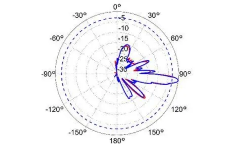
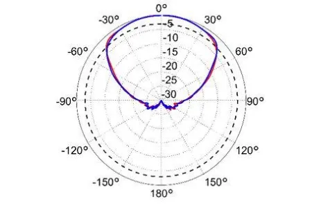
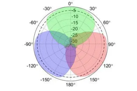
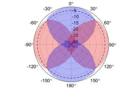
04
CN-ANT-120D-KIT
120-degree sectorized, 2-port external antenna for Celona outdoor access point
2-port sector antenna, 3300-4200 and 4400-5000 MHz, 120° HPBW
- High gain and slant dual polarization
- Simultaneously maximize coverage and minimize interference
- Ideal for 2-sector frequency-reuse one with LTE equipment
- Includes two surge protectors and two LMR400 120” / 3m antenna cables.
- Two required per Celona outdoor AP.
| Electrical Specification | |||
|---|---|---|---|
| Frequency Band | MHz | 3300 - 4200 | 4400 - 5000 |
| Gain | dBi | 15.5 | 16.5 |
| Polarization | Slant (±45°) | Slant (±45°) | |
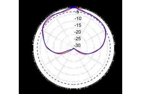
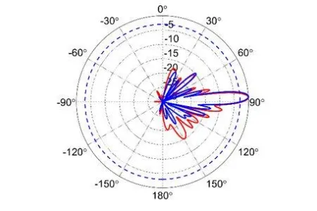
| Horizontal HPBW | Degree | 115 | 90 |
| Horizontal Squint | Degree | ±4 | ±3 |
| Vertical HPBW | Degree | 8±1 | 6.5±0.25 |
| Electrical Downtilt | Degree | 3.5 | 3.5 |
| Front-to-Back Ratio @ 180° | dB | 18 | 18 |
| Cross-polarization Ratio | dB | 15 | 15 |
| VSWR | 1.7 typ | 2 max | 1.3 typ | 1.5 max | |
| Port-to-Port Isolation | dB | 18 | 18 |
| Max. Input Power per Port | W | 50 | 50 |
| Impedance | Ohms | 50 | 50 |
| Bracket Specification | |
|---|---|
| Material Type | UPVC |
| Mechanical Tilt (Degree) | 0 - 15 |
| Mounting Type | Pipe Mount |
| Antenna Size | 920 × 155 × 85 mm |
| Antenna Weight | 5 kg |
| Mechanical Specifications | |
|---|---|
| RF Connector Type | Type N Female |
| RF Connector Quantity | 2 |
| RF Connector Position | Bottom of radome |
| Electrical Grounding | RF connector grounded to reflector and mounting bracket |
| Radome Material | UV resistant PVC |
| Ingress Protection | IP55 rain and dust resistant |
| Wind Load, frontal | 220N @ 160km/h | 49lbf @ 100mph |
| Max. Wind Speed | 160km/h | 100mph |
| Temperature Range | -40° to +60° C | -40° to +140° F |
| Sector Dimensions | |
|---|---|
| Length | 73.6cm / 29” |
| Width | 17.8cm / 7” |
| Height | 8.9cm / 3.5” |
| Net Weight, with brackets | 5 kg / 11 lb |
| Shipping Dimensions | |
|---|---|
| Length | 102cm / 40” |
| Width | 36cm / 14” |
| Height | 36cm / 14” |
| Net Weight | 9.5 kg / 21 lb |
| Measurement definitions | |
|---|---|
| HPBW | Average and variation of the antenna’s 3dB beamwidth (half power beamwidth) in its horizontal (Azimuth) or vertical (Elevation) pattern. |
| Horizontal Squint | Angle in the antenna’s azimuth pattern in which the maximum gain occurs. Reported is the maximum variation in the frequency band. |
| Electrical Downtilt | Angle in the antenna’s elevation pattern in which the maximum gain occurs. |
| Gain | Antenna’s average gain and variation in each frequency band. |
| Front to Back Ratio @ 180° | Difference between the antenna’s maximum gain and the gain directly behind the antenna (θ=180°). |
| Front to Back Ratio @ 180°±30° | Difference between the antenna’s maximum gain and the maximum gain in the antenna’s back lobe over ±30° angles. |
| Cross polarization at boresight | Difference between the co-polarization and cross-polarization gain at 0° (boresight). |
| Cross-polarization Ratio over HPBW (dB) | Maximum difference between the co-polarization and cross-polarization gain across the sector’s HPBW. |
05
CN-ANT-65D-KIT
65-degree sectorized, 2-port external antenna for Celona outdoor access point
2-port sector antenna, 3300-4200 and 4400-5000 MHz, 65° HPBW
- High gain and slant dual polarization
- Simultaneously maximize coverage and minimize interference
- Ideal for 3-sector frequency-reuse one with LTE equipment
- Includes two surge protectors and two LMR400 120” / 3m antenna cables
- Two required per Celona outdoor AP
| Electrical Specification | |||
|---|---|---|---|
| Frequency Band | MHz | 3300- 4200 | 4400 - 5000 |
| Gain | dBi | 17 | 18 |
| Polarization | Slant (±45°) | Slant (±45°) | |
| Horizontal HPBW | Degree | 63 ± 2 | 65 ± 2 |
| Horizontal Skew | Degree | ± 2 | ± 2 |
| Vertical HPBW | Degree | 6.5 ± 0.5 | 5.5 ± 0.5 |
| Electrical Downtilt | Degree | 3.5 | 3 |
| Front-to-Back Ratio @ 180° | dB | 35 | 38 |
| Front-to-Back Ratio @ 180°±30° | dB | 30 | 35 |
| Cross-polarization Ratio at Boresight | dB | 18 | 20 |
| Cross-polarization Ratio over HPBW | dB | 13 | 14 |
| VSWR | dB | 1.5 typ | 2 max | 1.5 typ | 1.7 max |
| Return Loss | 14 typ | 10 max | 14 typ | 12 max | |
| Port-to-Port Isolation | dB | 20 | 25 |
| Max. Input Power per Port | W | 50 | 50 |
| Impedance | Ohms | 50 | 50 |
| Bracket Specification | |
|---|---|
| Material Type | Hot Dipped Galvanized Steel |
| Mechanical Tilt (Degree) | -4 - 16 |
| Mounting Type | Pipe Mount |
| Mounting pole diameter | 2.5cm - 8.9cm / 1.25" - 3.5" |
| Antenna-to-Pipe Distance | 13.1cm / 5" |
| Bracket-to-Bracket Distance | 49cm / 19" |
| Mechanical Specifications | |
|---|---|
| RF Connector Type | Type N Female |
| RF Connector Quantity | 2 |
| RF Connector Position | Bottom of radome |
| Electrical Grounding | RF connector grounded to reflector and mounting bracket |
| Radome Material | UV resistant PVC |
| Ingress Protection | IP55 rain and dust resistant |
| Wind Load, frontal | 170N @ 160km/h | 38 lbf @ 100mph |
| Max. Wind Speed | 160km/h | 100mph |
| Temperature Range | -40° to +60° C | -40° to +140° F |
| Sector Dimensions | |
|---|---|
| Length | 73.6cm / 29” |
| Width | 17cm / 7” |
| Height | 8.9cm / 3.5” |
| Net Weight, with brackets | 4.5 kg / 10lb |
| Shipping Dimensions | |
|---|---|
| Length | 102cm / 40” |
| Width | 36cm / 14” |
| Height | 36cm / 14” |
| Net Weight | 8.2 kg / 16 lb |
| Measurement definitions | |
|---|---|
| HPBW | Average and variation of the antenna’s 3dB beamwidth (half power beamwidth) in its horizontal (Azimuth) or vertical (Elevation) pattern. |
| Azimuth Skew | Angle in the antenna’s azimuth pattern in which the maximum gain occurs. Reported is the maximum variation in the frequency band. |
| Electrical Downtilt | Angle in the antenna’s elevation pattern in which the maximum gain occurs. |
| Gain | Antenna’s average gain and variation in each frequency band. |
| Front to Back Ratio @ 180° | Difference between the antenna’s maximum gain and the gain directly behind the antenna (θ=180°). |
| Front to Back Ratio @ 180°±30° | Difference between the antenna’s maximum gain and the maximum gain in the antenna’s back lobe over ±30° angles. |
| Cross polarization at boresight | Difference between the co-polarization and cross-polarization gain at 0° (boresight). |
| Cross-polarization Ratio over HPBW (dB) | Maximum difference between the co-polarization and cross-polarization gain across the sector’s HPBW. |
06
CN-ANT-90D-4P
90-degree sectorized, 4-port external antenna for Celona outdoor access point
4-port sector antenna, 3300-3800 MHz, 90° HPBW
- High gain and slant dual polarization
- Simultaneously maximize coverage and minimize interference
- Ideal for 4-sector frequency-reuse two with LTE equipment and CBRS deployments
- Includes four surge protectors and four LMR400 120” / 3m antenna cables
- One required per Celona outdoor AP
| Electrical Specification | |||
|---|---|---|---|
| Frequency Band | MHz | 3300-3550 | 3550-3800 |
| Gain | dBi | 16.5 ± 0.5 | 17 ± 0.3 |
| Polarization | Slant (±45°) | Slant (±45°) | |
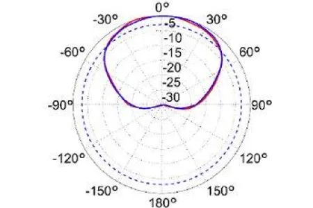
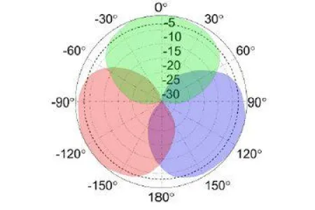
| Horizontal HPBW | Degree | 95 ± 5 | 90 ± 5 |
| Horizontal Skew | Degree | ±3 | ±3 |
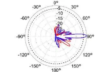
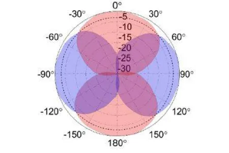
| Vertical HPBW | Degree | 6.5 ± 0.3 | 6 ± 0.3 |
| Electrical Downtilt | Degree | 0 | 0 |
| Front-to-Back Ratio @ 180°±30° | dB | 30 | 30 |
| Cross-polarization Ratio over HPBW | dB | 15 | 14 |
| VSWR | 1.5 typ | 2 max | 1.5 typ | 1.7 max | |
| Return Loss | dB | 14 typ | 10 max | 14 typ | 12 max |
| Port-to-Port Isolation | dB | 25 | 25 |
| Max. Input Power per Port | W | 50 | 50 |
| Impedance | Ohms | 50 | 50 |
| Bracket Specification | |
|---|---|
| Material Type | Power Coated Steel |
| Mechanical Tilt (Degree) | -2 - 8 |
| Mounting Type | Pipe Mount |
| Mounting pole diameter | 2.5cm - 8.9cm / 1.25" - 3.5" |
| Antenna-to-Pipe Distance | 7.6cm / 3" |
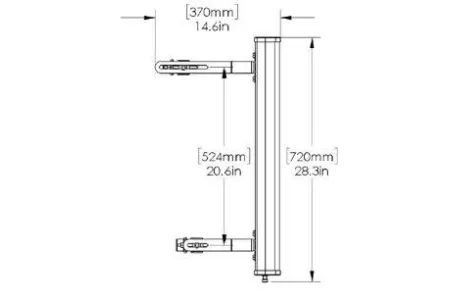
| Bracket-to-Bracket Distance | 52.4cm / 20.6" |
| Mechanical Specifications | |
|---|---|
| RF Connector Type | Type N Female |
| RF Connector Quantity | 4 |
| RF Connector Position | Bottom of radome |
| Electrical Grounding | RF connector grounded to reflector and mounting bracket |
| Radome Material | UV resistant PVC |
| Ingress Protection | IP55 rain and dust resistant |
| Wind Load, frontal | 240N @ 160km/h | 54 lbf @ 100mph |
| Max. Wind Speed | 160km/h | 100mph |
| Temperature Range | -40° to +60° C | -40° to +140° F |
| Sector Dimensions | |
|---|---|
| Length | 72cm / 28.3” |
| Width | 27.9cm / 11” |
| Height | 8.9cm / 3.5” |
| Net Weight, with brackets | 10 kg / 22 lb |
| Shipping Dimensions | |
|---|---|
| Length | 102cm / 40” |
| Width | 36cm / 14” |
| Height | 36cm / 14” |
| Net Weight | 13.6 kg / 30lb |
| Measurement definitions | |
|---|---|
| HPBW | Average and variation of the antenna’s 3dB beamwidth (half power beamwidth) in its horizontal (Azimuth) or vertical (Elevation) pattern. |
| Azimuth Skew | Angle in the antenna’s azimuth pattern in which the maximum gain occurs. Reported is the maximum variation in the frequency band. |
| Electrical Downtilt | Angle in the antenna’s elevation pattern in which the maximum gain occurs. |
| Gain | Antenna’s average gain and variation in each frequency band. |
| Front to Back Ratio @ 180°±30° | Difference between the antenna’s maximum gain and the maximum gain in the antenna’s back lobe over ±30° angles. |
| Cross-polarization Ratio over HPBW (dB) | Maximum difference between the co-polarization and cross-polarization gain across the sector’s HPBW. |
07
CN-ANT-GPS-KIT
Industrial grade GPS/GLNSS external timing antenna for Celona indoor access point
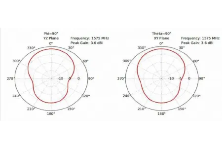
1.574 GHz to 1.61 GHz, 32 dBi GPS/GLNSS Timing Antenna
- High Selectivity Dual Filter RF Architecture • 0.75” NPT and 1”-14 Marine Mount Compatible
- Eliminated high Power RFI Operating within • UV Resistant / Cool Gray for Reduced Visibility Multi-Located Base Station Environment
- Mounts to standard pipe up to 1-0.5”
- Impact Resistant ASA Radome
- High grade stainless steel and Dacron
- Rugged Die-Cast Aluminum Base plated steel mounting clamps
- Integrated Bulkhead, TNC Jack • Includes surge protector, cables (75ft, 15ft) and mounting brackets
- IP67 Rated
| Electrical Specification | Minimum | Typical | Maximum | |
|---|---|---|---|---|
| Frequency Range | MHz | 1,574 | 1,610 | |
| Output VSWR | 2:1 | |||
| Impedance | Ohms | 50 | ||
| Gain | dBi | 32 | ||
| Gain Variation | dBi | ±3 | ||
| Noise Figure | dB | 3.1 | 3.5 | |
| Out Of Band Rejection | dB | 70 | ||
| Operating DC Voltage | Volts | 2.7 | 5.5 | |
| Current | mA | 7 | 15 |
| Mechanical Specifications | |
|---|---|
| Connector Type | TNC Female |
| Housing Plating / Color | Gray |
| Mounting Application | 0.75’’ NPT 316 SS Pipe |
| Operating Range | -40 °C to +85 °C |
| Data Wind Survivability CN-ANT | Sheet 150 MPH (241.4 KPH) -GPS-KIT, industrial grade GPS/GLNSS exte |
| timing a Humidity | ntenna for Celona indoor access point 95% |
| Unit Dimensions | |
|---|---|
| Base Diameter | 8.9cm / 3.5” |
| Height | 12.4cm / 4.9” |
| Weight | 6.8 kg / 15 lb |
| Shipping Dimensions | |
|---|---|
| Length | 30.5cm / 12” |
| Width | 30.5cm / 12” |
| Height | 25.4cm / 10” |
| Net Weight | 6.8 kg / 15 lb |
| Measurement definitions | |
|---|---|
| Electrical Downtilt | Angle in the antenna’s elevation pattern in which the maximum gain occurs. |
| Gain | Antenna’s average gain. |
| Front to Back Ratio @ 180°±30° | Difference between the antenna’s maximum gain and the maximum gain in the antenna’s back lobe over ±30° angles. |
| Cross polarization Ration (dB) | Typical difference between the co-polarization and cross-polarization gain across the sector’s 3 dB Beam width. |
08
CN-PTP-GM-KIT
PTP Grandmaster Clock to be used in indoor deployments for access points to be phase synchronized
PTP Grandmaster Clock designed for small cell, 4G and 5G deployments
- IEEE-1588 PTP Grandmaster Clock
- Multiple PTP Profiles (G.8265.1, G.8275.1, G.8275.2, Telecom-2008 Profile, 802.1AS, Enterprise Profile, Broadcast Profile SMPTE)
- Multi-Constellation (GPS, GLONASS, Beidou & Galileo)
- 15ns (1-sigma) time accuracy relative to GNSS reference
- Includes power adapter, bullet 360 antenna, 75-ft & 12-ft cables and surge protector
- Holdover of ±1.5us over 4hours (constant temperature and when locked to GPS for 7 days)
- Inputs: GNSS, 1588-PTP and SyncE
- Outputs: 1588-PTP, NTP, SyncE, PPS, and 10MHz
- Dedicated management port (1xRJ45)
- Network Management: SNMP, Web UI, CLI
- VLAN support
- IPv4 and IPv6
| General Specifications | |
|---|---|
| Inputs | GNSS, 1588-PTP, SyncE |
| Outputs | PPS, 10MHz, NTP, PTP, SyncE |
| Ethernet Ports | 1x Mgmt RJ45 1x 1G SFP 1x 1G RJ45 |
| Protocols | PTP, NTP & SyncE |
| GNSS Antenna | SMA |
| Protocols: | IEEE-1588 (PTP), NTPv4, SyncE, IPv4, IPv6, TELNET, SFTP, SSH, RADIUS, TACACS+, SNMP, DAYTIME, TIME |
| Network management | SNMPv2, v3, HTTPS, CLI |
| User Interfaces: | CLI : Monitoring and Management Web UI :Monitoring and Management |
| Regulatory & Standards | |
|---|---|
| Operating Temperature | -40°C to +85°C |
| Operating Humidity | 5%-95% RH non-condensing (+60°C) |
| Storage temperature | -55°C to +105°C |
| Safety & Health | UL EN 62368-1 CE, CISPR32 class A GR-63; Level 3 ETSI (EN55032/EN55024) EN 300019, Class T3.2 |
| Electrical | EMC, ESD Immunity & susceptibility FCC Part 15 Class B / ICES 003 Class-B Korea KN32 / KN35 Class A EN 301 489-1, EN 301 489-19 EN 303 413 IEEE 1613-1 Telcordia GR-1089 |
| Synchronization: | ITU: G.8265.x, G.8275.x (PRTC/T-GM) IEEE : PTP (IEEE 1588v2) IETF :NTPv4 (RFC5905) |
| Product compliance: | 2014/53/EU (RED Directive) 2011/65/EU (RoHS2 Directive) 2012/19/EU (WEEE Directive) |
| Performance | |
|---|---|
| Time of day accuracy | 15ns (1-sigma) reference GNSS |
| Time stamp accuracy | <10 ns rms |
| Frequency accuracy | 1.16x10^(-12) (one day ave.) Holdover: <1x10^(-10) /24hrs |
| Tracking to GPS | <15ns (locked) Holdover: < ±1.5μs/4hrs (7 days locked) |
| Power consumption | 5W average, 10W maximum |
| Physical Characteristics | |
|---|---|
| Length | 20.8cm / 8.2” |
| Width | 20cm / 7.9” |
| Height | 4.4cm / 1.7” |
| Weight | 3kg / 6 lb |
| Power | |
|---|---|
| DC Power, dual feed | -36VDC to -72VDC |
| Current consumption | 330mA (max) |
09
C-PTP-GM-PLUS-KIT
Scalable PTP Grandmaster Clock for indoor deployments, supporting phase synchronization for up to 100 access points
PTP Grandmaster Clock designed for small cell, 4G and 5G deployments
- IEEE-1588 PTP Grandmaster Clock
- Supports multiple PTP Profiles: ITU-T G.8265.1, G.8275.1, G.8275.2, Telecom-2019 Profile, IEEE 802.1AS, Enterprise Profile, Power Profile (C37.238 2011, C37.238-2017)Multi-Constellation (GPS, GLONASS, Beidou & Galileo)
- GNSS Precision Timing
- Dual-frequency GNSS (L1 & L5)
- Multi-Constellation support (GPS, GLONASS, Beidou, Galileo)
- <5ns (1-sigma) time stability when tracking GNSS
- Anti-jamming and anti-spoofing features
- Timing Accuracy and Holdover
- 5ns time stability relative to GNSS reference
- Holdover: ±1.5µs over 4 hours (when locked to GPS for 7 days)
- I/O and Connectivity
- Inputs: GNSS Antenna, 1588-PTP, PPS, SyncE
- Outputs: 1588-PTP, NTP, SNTP, SyncE, PPS, ToD, 10MHz
- Ethernet Ports: 4 x 1G/10G SFP+, 2 x 10/100/1000 BASE-T RJ45 (PoE+ available on ETH0)
- SMA connectors for GNSS Antenna, PPS_IN, PPS_OUT, CLK, FREQ, ToD
- Network Management and Protocols
- Management: SNMPv2/v3, Web UI (HTTPS), CLI, NETCONF, RESTCONF
- Protocols: PTP (IEEE 1588v2.1), NTPv4, SNTPv4, SyncE, IPv4, IPv6
- Physical Characteristics
- Compact 19” half-rack form factor (1U) - 20.8 x 20 x 4.4 cm
- Dual DC Power (-36VDC to -72VDC), PoE+ PD (optional, up to 25W)
- Operating temperature: -40°C to +50°C
- Compliance and Standards
- Safety: UL EN 62368-1, CE
- EMC: FCC Part 15 Class A, EN 301 489-1, EN 301 489-19
- Environmental: RoHS, WEEE compliant
| General Specifications | |
|---|---|
| Inputs | GNSS, 1588-PTP, SyncE |
| Outputs | PPS, 10MHz, NTP, PTP, SyncE |
| Ethernet Ports | 4x 1G/10G SFP+, 2x 10/100/1000 BASE-T RJ45 (POE+ available) |
| Protocols | PTP, NTP & SyncE |
| GNSS Antenna | SMA (Female) |
| Protocols: | IEEE-1588 (PTP), NTPv4, SNTPv4, SyncE, IPv4/IPv6, SNMP, SSH, RADIUS, TACACS+ |
| Network management | CLI, Web UI (HTTPS), SNMPv2/v3, NETCONF, RESTCONF |
| User Interfaces: | CLI : Monitoring and Management Web UI :Monitoring and Management |
| Regulatory & Standards | |
|---|---|
| Operating Temperature | -40°C to +50°C |
| Operating Humidity | 5%-95% RH non-condensing (+60°C) |
| Storage temperature | -55°C to +105°C |
| Safety & Health | UL EN 62368-1 CE, CISPR32 class A GR-63; Level 3 ETSI (EN55032/EN55024) EN 300019, Class T3.2 |
| Electrical | EMC, ESD Immunity & susceptibility FCC Part 15 Class B / ICES 003 Class-B Korea KN32 / KN35 Class A EN 301 489-1, EN 301 489-19 EN 303 413 IEEE 1613-1 Telcordia GR-1089 |
| Synchronization: | ITU: G.8265.x, G.8275.x (PRTC/T-GM) IEEE : PTP (IEEE 1588v2) IETF :NTPv4 (RFC5905) |
| Product compliance: | 2014/53/EU (RED Directive) 2011/65/EU (RoHS2 Directive) 2012/19/EU (WEEE Directive) |
| Performance | |
|---|---|
| Time of day accuracy | 15ns (1-sigma) reference GNSS |
| Time stamp accuracy | <10 ns rms |
| Frequency stability | 1.16x10^(-12) (one-day average) |
| Tracking to GNSS | <15ns (locked) Holdover: < ±1.5μs/4hrs (7 days locked) |
| Power consumption | 18-20W, POE+ option (25W max) |
| Physical Characteristics | |
|---|---|
| Length | 20.8cm / 8.2” |
| Width | 20cm / 7.9” |
| Height | 4.4cm / 1.7” |
| Power | |
|---|---|
| DC Power, dual feed | -36VDC to -72VDC |
| Current consumption | 500mA (max) |
10
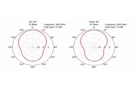
Bullet ™ 360 GPS Antenna
| Environmental specifiations | |
|---|---|
| Operating Temperature | -40°C to +90°C |
| Storage Temperature | -40°C to +90°C |
| Vibration | 10 - 200 Hz Log sweep 3g (Sweep time 30 minutes) 3 axes |
| Shock | 50g vertical, 30g all axes |
| Humidity Soak | +60°C @ 95% RH, 96 hours |
| Corrosion Salt Resistant | 5% Salt spray tested, 96 hours |
| Technical / performance specifications | 3.3V | 5.0V |
|---|---|---|
| Prime Power | 3.3V DV (±10%) | 5.0V DV (±10%) |
| Power Consumption | <13mA | <20mA |
| Gain | 26dB ± 3dB (GPS) | 28dB ± 3dB (GPS) |
| Output Impedance | 50Ω | |
| Frequency | GPS L1 1575.42 ±3MHz BDS B1 1561 ±3MHz GLO G1 1602 ±3MHz | |
| VSWR | 2.0 maximum | |
| Axial ratio | <5dB (GPS) <3dB | |
| Noise | 2.0dB (typical) | |
| Bandwidth (10dB RL) | 70 MHz (min) | |
| Out of Band rejection | fo= L1, B1, G1 fo ±50 MHz: 30 dB typ fo ±100MHz: 40dB typ | |
| Azimuth coverage | 360° (omni-directional) | 360° (omni-directional) |
| Elevation coverage | 0°-90° elevation (hemispherical) | 0°-90° elevation (hemispherical) |
| ESD | IEC 61000-4-2 |
| Phyiscal charcteristics - 3.3v & 5v dc antennas | |
|---|---|
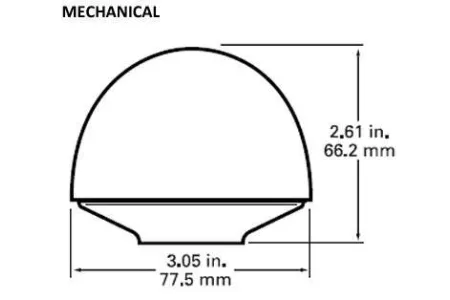
| Dimensions | 3.05”D x 2.61” H (77.5mm x 66.2mm) |
| Weight | 7.0oz (200grams) |
| Enclosure | Off-white plastic |
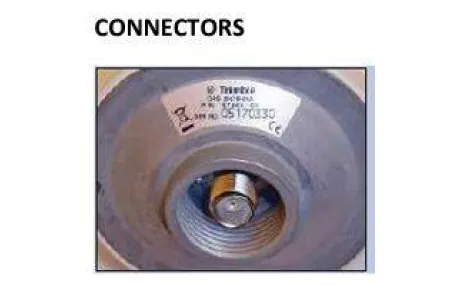
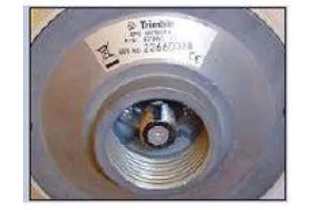
| Connector | F-type & TNC (5V) - TNC (3.3V only) |
| Mounting | 1” - 14” thread or ¾” pipe thread |
11
CN-ANT-SPL
The Celona CN-ANT-SPL is a purpose-built antenna splitter designed for use with Celona 5G Outdoor AP21 units. It supports the deployment of sectoral antennas, enabling enhanced and optimized coverage for outdoor private 5G environments. For 4-sector deployments, 2 splitters are required per AP21. Typical use cases include oil & gas, utilities, mining, and large campus environments requiring robust and scalable outdoor 5G coverage.
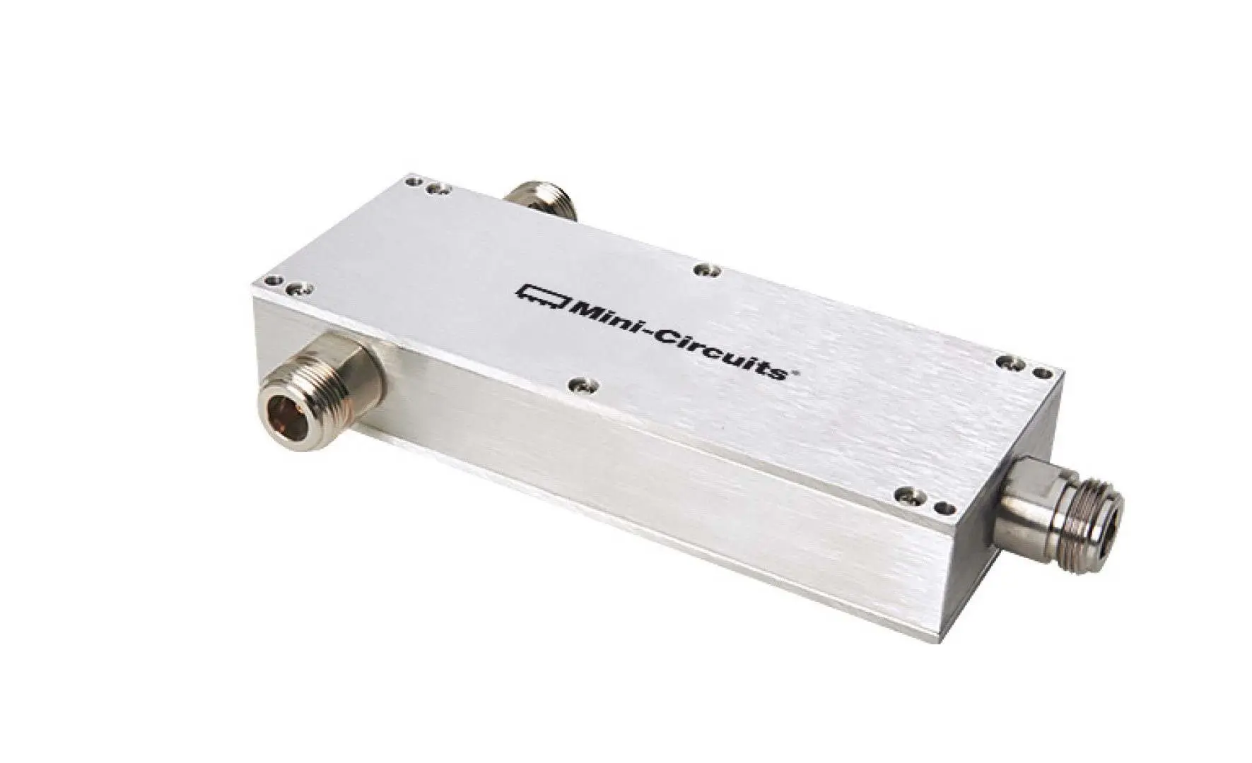
| Key Features | |
|---|---|
| Part Number | CN-ANT-SPL |
| Compatibility | Celona 5G Outdoor AP21 |
| Function | 2-way splitter for external sector antennas |
| Connector Type | N-Type (female) |
| Impedance | 50 Ω |
| Frequency Range | 600 MHz to 6000 MHz |
| Power Handling | Up to 30W (when used as splitter) |
| Insertion Loss | ≤ 0.8 dB (typical) |
| DC Pass | 200 mA per port (400 mA total) |
| Isolation | ≥ 19 dB (typical) |
| Housing | Rugged aluminum alloy, outdoor-rated |
| Mounting | Compatible with AP21 mounting kits |
| Operating Temperature | -55°C to +60°C |
| Compliance | RoHS, CE, FCC |
Applications
- Sectorized antenna deployments for AP21
- Extended outdoor coverage for private 5G
- Oil & gas, utilities, mining, and
Ordering information
| Ordering information | |
|---|---|
| CN-ANT-SPL | Celona Antenna Splitter for 5G Outdoor AP21 |
12
Celona 5G Airkit with Indoor AP22
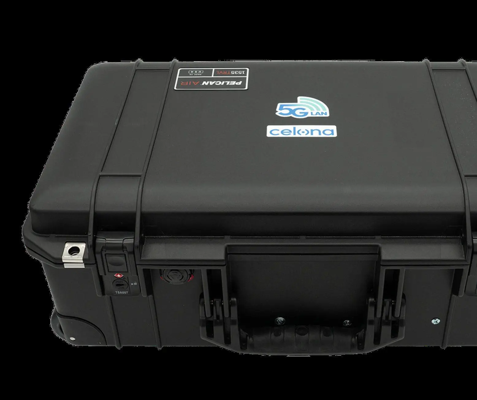
The Celona 5G Airkit, built with the Celona Indoor 5G AP22, is a portable, end-to-end private 5G solution designed for demo and showcase environments, providing private 5G connectivity for enterprise applications. This kit includes a 3-year subscription to Celona’s private wireless services, powered by Celona Edge software and the Celona Orchestrator cloud for seamless SIM provisioning and management.
| RF Specifications (5G) | |
|---|---|
| MIMO Configuration | 2x2 MIMO UL/DL, supporting up to 256 QAM Modulation |
| Antenna | Built-in omnidirectional, max gain of 6 dBi |
| Specifications | |
|---|---|
| Compliance | 3GPP Release 15 TDD |
| Power | Transmit Power: Up to 24 dBm per port Power Supply: PoE injector included (AC to PoE power) |
| Network Domain Support | Internal IP Domain |
| Performance and Capacity | Latency: <10ms one-way Concurrent Connections: Up to 128 active devices |
| Physical Dimensions (Airkit) | Size: 17.6 x 13.9 x 6.9 inches (447 x 353 x 176 mm) Weight: 30 lbs (13.6 kg) |
| Timing and Synchronization | PTP Grandmaster & IEEE 1588v2 PTP: Free running |
| Compliance and Certifications | AP22-48: FCC AP22-78: CE AP22-77: CE |
| Frequency Band Support | AP22-48 3.55-3.7 GHz AP22-78 3.3-3.8 GHz AP22-77 3.8-4.2 GHz |
| AP LED Indicators | System LED: Displays system status 5G LED: Indicates 5G connection status |
5G Airkit Bring-Up Instructions
- Power On: Connect the Airkit using the appropriate regional power plugs.
- Assign AP and Edge: Ensure they are assigned to the customer orchestrator account and appear in the inventory.
- Edge Cluster Creation: https://docs.celona.io/en/articles/7132992-edge-cluster-creation
- Create a New Site: https://docs.celona.io/en/articles/7133069-create-a-new-site
- Activate Celona Access Points: https://docs.celona.io/en/articles/7133150-activating-celona-access-points
- LED Status: Wait until the 5G Airkit AP LEDs (system and 5G) turn solid blue (approx. 30 minutes).
- Activate Devices and SIMs: Attach devices to the Celona 5G network. https://docs.celona.io/en/articles/7132329-celona-sim-lifecycle-management
- Operational Status: Once LEDs are blue, the 5G Airkit is fully operational.
Key Components
- 5G Indoor n78 Access Point (3300-3800 MHz)
- E100 Mini Edge Device
- Celona Orchestrator (Cloud service)
- 20 Private SIM Cards
- Power Cable and International Plug(s)
- Celona Express Technical Support
- Limited Lifetime Warranty
Ordering information
3-year indoor 5G private wireless service subscription for one portable air kit including SIM provisioning, mobile core services via Celona Edge software, and Celona Orchestrator cloud services.
| Ordering information | |
|---|---|
| C-S-AIRKIT-5G-48-NN-X-3 | The air kit includes a 5G category A n48 (3550-3700 MHz) access point with integrated antennas, E100 Edge, switch, Celona Express technical support, limited lifetime warranty, and 20 private SIM cards. |
| C-S-AIRKIT-5G-78-NN-X-3 | The air kit includes a 5G indoor n78 (3300-3800 MHz) access point with integrated antennas, E100 Edge, switch, Celona Express technical support, limited lifetime warranty, and 20 private SIM cards. |
| C-S-AIRKIT-5G-77-NN-X-3 | The air kit includes a 5G indoor n77 (3800-4200 MHz) access point with integrated antennas, E100 Edge, switch, Celona Express technical support, limited lifetime warranty, and 20 private SIM cards. |
13
Summary
The Celona 5G Airkit with AP22, certified for the US, EU, and UK, is optimized for rapid deployment in demos and showcases, providing flexible and high-performance private 5G connectivity for enterprises.