
AP 21 installation guide
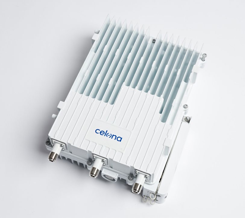
How to mount, ground and provision the Celona AP 21 ruggedized outdoor access point - pole and wall installations, GPS antenna and cable selection, and weatherproofing the connections.
01
Installation preparation
Personnel & safety
Celona recommends reviewing this entire guide before starting. Installing the AP on a cell tower, building or other structure may require at least two people or a qualified tower crew.
Installation personnel must follow standard safety precautions for working at height and with electricity, and any other applicable regulations.
Network design plan
Each cell site differs in the type and number of components, the coverage area and the user requirements. Identify the structure the equipment will mount to, the intended height of the AP and antenna, the antenna down-tilt, and any other factor that affects the installation. AP 21 operates in single-carrier mode using ANT0 and ANT1.
Total output EIRP for AP21-48 is governed by FCC Part 96 - power is calculated and regulated automatically by Celona software.
Materials & tools
| Item | Description |
|---|---|
| Power cable | < AWG16, for example AWG14 |
| RF antenna cable | 50-ohm feeder |
| RF antenna | Omni or directional |
| Optical fibre | Single-mode, for SFP backhaul |
| Ground cable | Yellow-green, at least 6 AWG (10 mm²) |
What’s in the box
Check the packaging is neither damaged nor wet. If it is, or if anything is missing, contact support@celona.io before proceeding.
| Item | Qty and description |
|---|---|
| AP 21 unit | 1 - confirm the tag on the unit matches the model ordered |
| Power adaptor | 1 - 48 V DC, AC adapter and power surge protector included |
| Power terminal | 1 - two-wire green terminal |
| Power plug | 1 - US, EU or UK depending on the AP 21 SKU |
| Optical module | 2 - SFP LC, requires dual-strand fibre |
| GPS antenna kit | 1 - GPS antenna, fixing accessories, M4 screws, GPS jumper cable |
| Installation bracket kit | 1 - bracket, omega clamps, M10 bolts, gaskets and nuts |
The spare SFP shipped with the AP 21 is a convenience item and may not be accepted by every switch. For production, install the switch vendor’s approved optics.
Interfaces
| Interface | Description |
|---|---|
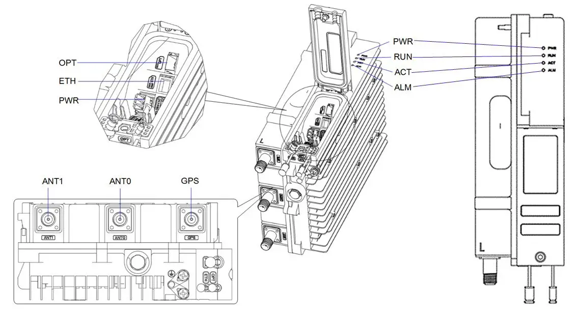
| PWR | Power supply: −48 VDC (−60 V to −42 V) |
| GPS | Port for the optional external GPS antenna, N-female connector |
| ANT0 | Port for external RF antenna 0, N-female connector |
| ANT1 | Port for external RF antenna 1, N-female connector |
| OPT | Optical backhaul interface to the external transmission network |
| ETH | RJ-45 interface, used for debugging or data backhaul |
LED status
| LED | Meaning |
|---|---|
| PWR | Green steady on: power is on. Off: no power supply |
| ACT | Green steady on: the cell is activated. Off: the cell is not activated |
| RUN | Fast flash (0.125 s): hardware alarm, e.g. VSWR. Slow flash (1 s): software initialising. Off: no power input, or faulty board |
| ALM | Red steady on: hardware alarm, e.g. VSWR. Off: no alarm |
02
Location and environment
AP 21 mounts on a pole or a wall. For the best coverage, place it in an unobstructed location.
Alongside network planning, weigh climate, hydrology, geology, earthquake risk, reliable electric power and transport access. Avoid extreme temperatures, harmful gases, unstable voltages, heavy vibration, loud noise, flames, explosives and electromagnetic interference such as large radar stations or transformer substations. Avoid anywhere prone to standing water, soaking, leakage or condensation. The AP is certified for Class 1, Division 2 hazardous-location installation.
Environmental specifications
| Item | Specification |
|---|---|
| Operating temperature | −22°F to 131°F / −30°C to 55°C |
| Mounting | Pole (40-100 mm diameter) or wall |
| Hazardous location | Class 1, Division 2 certified |
Grounding and lightning protection
Protect the AP 21, the antenna and the GPS against lightning.
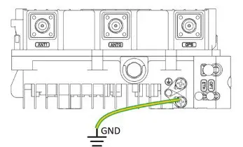
- The yellow-green ground wire must be at least 6 AWG (10 mm²) in diameter.
- Place the grounding as near as possible to the equipment.
- Connect to a reliable outdoor grounding point (earth) using one ground screw.
- The connection between grounding points and ground bar must be tight and reliable. Rustproof the terminals, for example with antioxidant coating or grease.
03
Process overview
Some cell sites already have a framework for attaching the AP and antenna. This guide assumes the AP mounts on a support pole or a wall.
- Install the GPS antenna on the AP.
- Install the AP on the pole or wall.
- Mount the antenna equipment.
- Connect the Ethernet and ground cables.
- Power on the device.
- Check the LEDs.
04
Weatherproofing
To protect the connection points from weather, clean each connection before fitting cold shrink tubes.
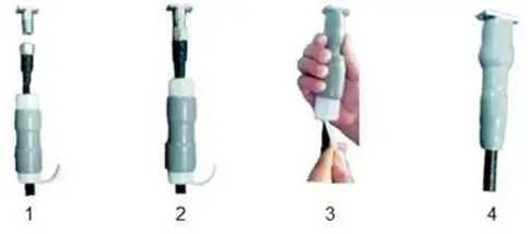
- Insert the cable into the cold shrink tube.
- Tighten the connector.
- Push the cold shrink tube to the top joint and pull out the strip.
- Check the cold shrink tube is tightly fitted to the connection.
05
Install GPS antenna
GPS works best with clear line of sight to the sky. Make sure the space above is at least 45 degrees unblocked by buildings.
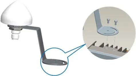
- Avoid installing the GPS antenna near other transmitting or receiving devices, to avoid interference.
- Insert the GPS jumper into a cold shrink tube, then connect one end to the GPS antenna.
- Push the cold shrink tube to the top joint and pull out the strip.
- Connect the other end of the GPS jumper to the GPS interface on the AP, which also needs weatherproof protection.
06
Install AP on pole or wall
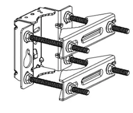
The mounting bracket is assembled before packing and comes in two parts: the bracket pre-assembled on the back of the device, and the pole or wall mounting bracket.
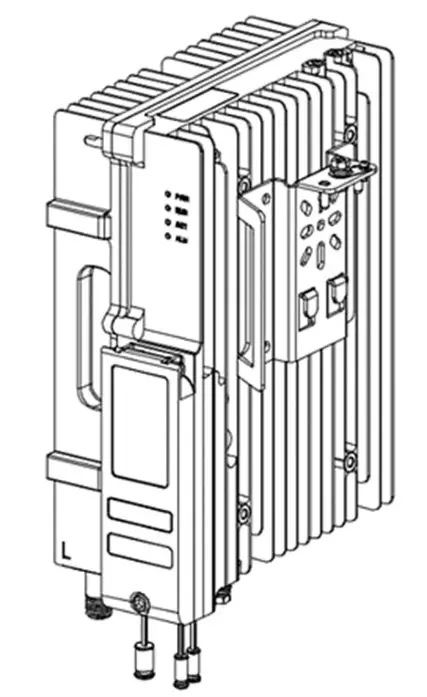
Pole mount
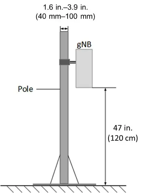
The pole diameter must be 1.6-3.9 in (40-100 mm), and the AP should sit at least 47 in (120 cm) up the pole.
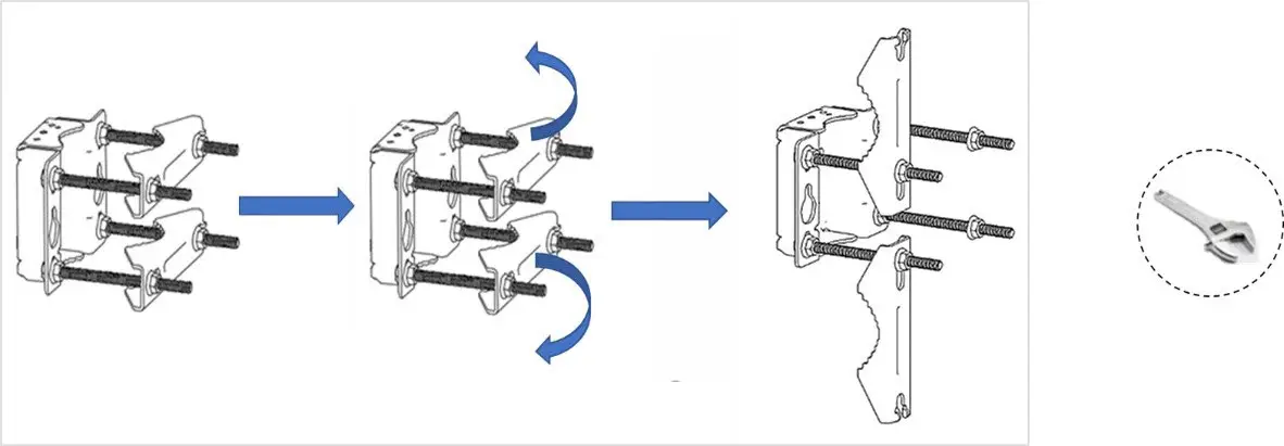
- Unscrew the nuts of the pole mounting bracket, slide the two clamps to the left, and turn them up or down.
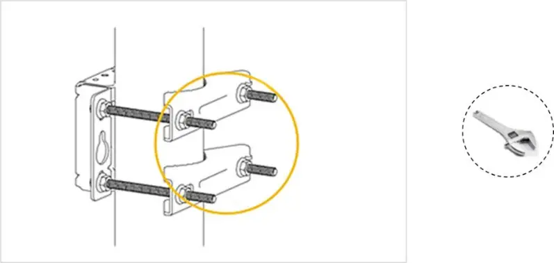
- Place the bracket against the pole and return the clamps to horizontal. Slide the clamp right and retighten the nuts.
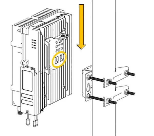
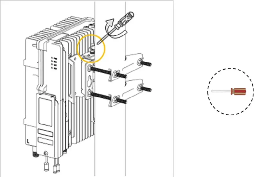
- Hold the AP 21 vertically and align the two pins on its bracket with the pin holes on the pole bracket. Push down until the hooks attach firmly to the slots.
- Tighten the bolt and screw on top of the AP 21 with a Phillips-head screwdriver.
Wall mount
Make sure the wall can bear at least four times the weight of the AP 21.
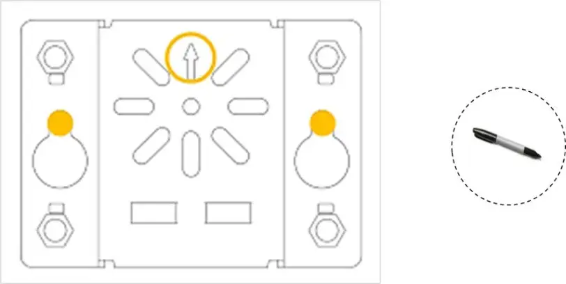
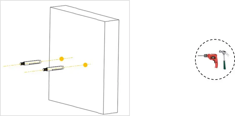
- Place the wall mounting bracket on the wall with the arrow pointing up and mark the drilling locations.
- Drill two holes 0.4 in (10 mm) in diameter and 2.8 in (70 mm) deep at the marks, then insert expansion bolts.
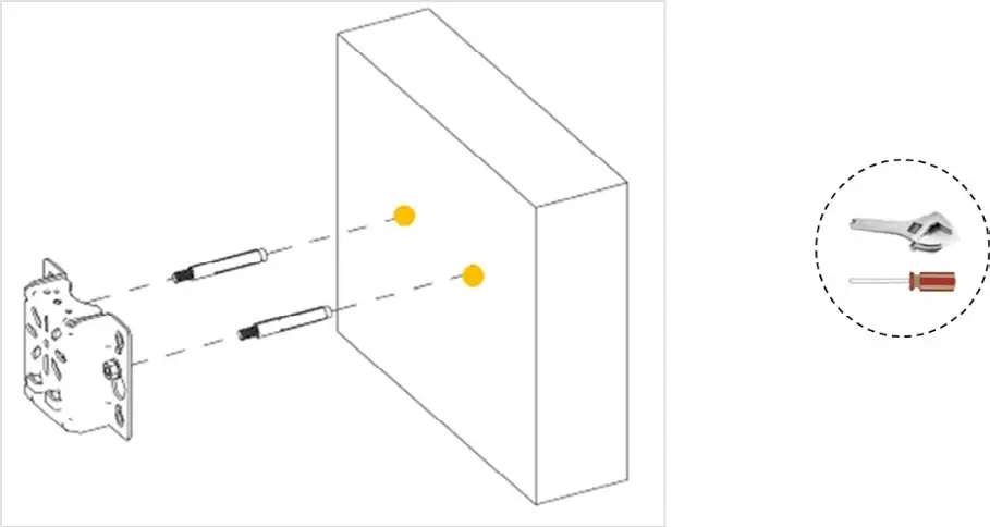
- Hang the bracket on the expansion bolts and fasten with flat washers, spring washers and nuts.
- Hold the AP 21 vertically, align the pins with the pin holes, push down until the hooks engage, then tighten the screw.
07
Connect cables
General requirements
- Bending radius of antenna feeder cable: 7/8 in > 250 mm, 4/5 in > 380 mm.
- Bending radius of jumper cable: 1/4 in > 35 mm, 1/2 in super-soft > 50 mm, 1/2 in ordinary > 127 mm.
- Bending radius of power and grounding cable: more than three times the cable diameter.
- Minimum bending radius of optical fibre: 20 times the fibre diameter.
- Bind cables by type. Intertwining and crossing degrade performance and are not permitted. Attach an identification label once the cable is laid.
GPS antenna cable
- Insert the GPS jumper into a cold shrink tube.
- Connect one end of the jumper to the GPS antenna.
- Push the cold shrink tube to the top joint and pull out the strip.
- Connect the other end to the GPS interface on the AP, and weatherproof it.
Power connector
Cable length varies by site, so both ends of the power adaptor are bare terminals. Make the power cable to the site measurements and fit the power plug and power terminal. Strip 0.47 in (12 mm) of insulation. Keep the power cord under 330 ft (100 m).
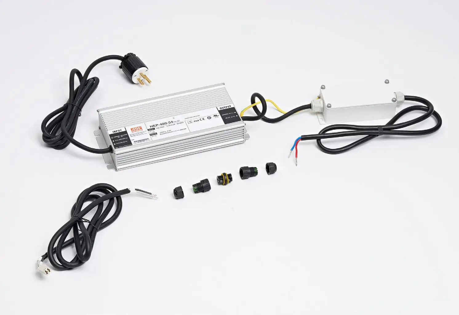
- Assemble the power plug on the input end, connecting live and ground to the labelled terminals, and tighten the screws.
- Assemble the power terminal on the output end, connecting live and neutral.
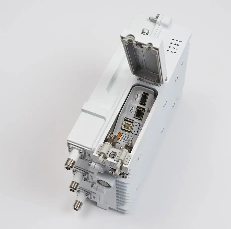
- Connect the power cable to the PWR interface in the wiring cavity, running it along the lint slot and out through the PWR port.
- Connect the adaptor input to the outlet. If the outlet is outdoors, place the adaptor in a waterproof box.
Ground cable
Prepare the grounding cable to the measurements and requirements of the specific site. The AP 21 has two grounding screws on the bottom of the unit. Unscrew one, connect one end of the ground cable, and fasten it again.
08
Install antenna feeder system
There are two kinds of outdoor antenna, omni-directional and directional.
Omni-directional
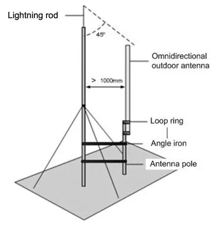
- The pole diameter should be 1.4 in / 35 mm to 2 in / 50 mm - typically a 50 mm round steel pole, depending on the antenna type.
- After fitting, the top of the pole and the clamp beneath the antenna should sit at the same level.
- Mount the antenna high enough to meet the coverage requirement, with the antenna top inside the 45-degree safety angle towards an independent lightning rod.
- Where an independent lightning rod is not possible, keep the pole supporting the lightning rod at least 1 m from the omnidirectional antenna.
Directional
Assemble the directional antenna, then fix the pole vertically to the ground or to concrete pillars on a rooftop using expansion screws. Fasten the pole with steel wires and mount the antenna on the pole using the installation rack.
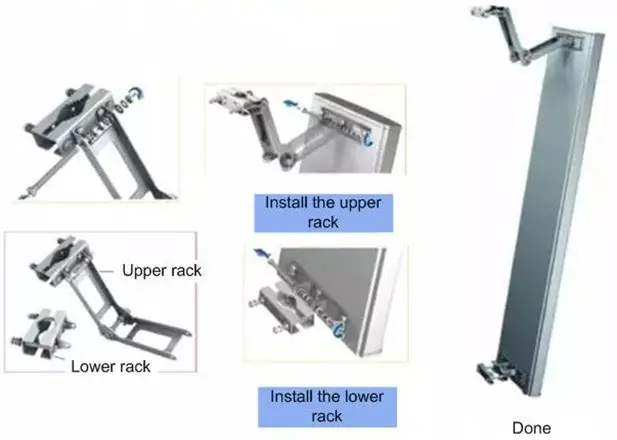
To lift the antenna assembly to a tower platform, use a pulley. Follow standard safety rules when working at height.
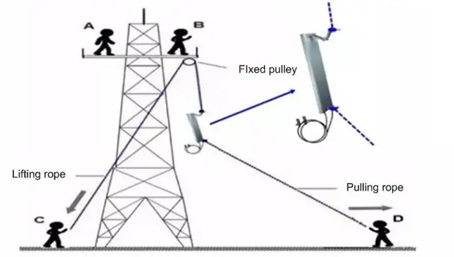
Once the AP is in position, connect all cables and wires. Seal and weatherproof every connection after testing has completed successfully.
Splitters (CN-ANT-SPL)
Use splitters to extend directional coverage from one AP across sector antennas. Budget insertion loss - roughly 3 dB per leg for a two-way split - plus cable loss when setting EIRP, then adjust AP power and verify cell-edge levels. Weather-seal all ports and connectors with butyl and cold-shrink or self-fusing tape.
09
Power on and check status
Power on to check LEDs
Power on the AP and check that the LED indicators are lighting as expected. Refer to the LED descriptions detailed earlier in this guide.
Checking AP status
The Celona AP 21 is designed to be plug-and-play, and therefore arrives pre-configured. The status is inferred by the LEDs and subsequently by connecting a mobile device to the Celona AP. A properly connected AP will show the Celona logo as the operator on the mobile’s screen.
10
Certified professional installation
The Celona AP 21 is a Class-B, FCC Part 96 certified device. Class-B devices must be installed by a Certified Professional Installer (CPI) - an FCC-approved person with the legal authority to validate and confirm the installation with a digital signature.
The CPI records the following for each AP 21, and signs it off while in current standing:
- GPS coordinates: latitude, longitude, height, and height type (above sea level or above ground level).
- Antenna details: azimuth, down-tilt, gain, EIRP capability (conductive power), beamwidth and model.
The CPI information is packaged with the AP’s FCC ID and the operator’s ID, signed with the CPI’s private key, and uploaded per AP to the Celona Orchestrator over HTTPS. Celona Edge uses it when registering the AP with the Spectrum Manager.
11
AP 21 capabilities and architecture
About the AP
The Celona AP 21 is a 3GPP Release 15 compliant integrated 5G NR access point with external antenna support, operating within the 3300-4200 MHz spectrum band. AP 21 supports 2x2 MIMO (multiple-input, multiple-output) and up to 256-QAM modulation, and can be pole or wall mounted. Powered by CelonaOS, AP 21 supports AerFlex - AP-only deployments with zero on-site infrastructure.
System architecture
The system consists of the essential functions for a private 5G NR network. The Celona Orchestrator performs AP authentication, validates the AP’s serial number, determines the network the AP needs to connect to, and finally directs the Celona AP 21 to the serving Celona Edge.
Each Celona AP 21 obtains service via its serving Celona Edge. The Celona Edge registers the AP, arbitrates spectrum with an FCC-approved Spectrum Manager, and algorithmically determines the most optimal radio parameters for the AP. The Celona Edge is aware of the AP’s location and its surrounding radio environment automatically. Once the AP is admitted by the Celona Edge, it can commence radio transmissions and service mobile stations.
Capabilities
The AP is a 5G NR small cell. It hosts functions to provide the following services:
- Resource management: admission control, flow control.
- Encryption of user data and control streams.
- Registering mobile stations with Celona Edge for voice and data services.
- Data only, voice only, or data and voice service.
- Paging mobile stations that are in power save mode.
- Fairness in allocation of resources across multiple mobile stations, in the uplink and downlink directions.
- Measurement configurations and handling of mobility of mobile stations.
Discovery
The Celona AP 21 supports zero-touch provisioning. The AP is preconfigured with the details necessary to discover the Celona Orchestrator and the Celona Edge automatically. After the Domain Proxy discovers the Orchestrator and the Edge, the AP is provisioned with operational parameters and authorised to transmit. The Celona Edge alone controls the radio frequency transmission of the AP. Once operational, the AP can provide services to mobile stations, which can connect to the packet data network as well as voice and multimedia networks via the Celona Edge. User data and control signals are encrypted, and the AP’s performance is periodically monitored by the Celona Edge with operational parameters continually optimised.
12
Radio, coverage and mobility
Radio access technology
Celona AP 21 implements an extensive set of 3GPP worldwide standards to provide advanced, 5th-generation packet radio service to mobile stations.
| Item | Specification |
|---|---|
| Type | 5G Ruggedized Access Point (3GPP Rel. 15 TDD) |
| RF specifications | 2x2 MIMO UL/DL, up to 256 QAM modulation |
| Channel bandwidth | 10/20/40/60/80/100 MHz |
Frequency band support (SKUs)
Supported operational frequencies by AP 21 model:
| Model | Frequency range |
|---|---|
| AP21-48 | 3.55-3.7 GHz |
| AP21-78H | 3.6-3.8 GHz |
| AP21-77 | 3.8-4.2 GHz |
| AP21-78L | 3.3-3.6 GHz |
| AP21-79 | 4.6-4.9 GHz |
Supported system bandwidth
The Celona AP 21 supports only one cellular sector. The combinations of system bandwidth possible depend on the authorisation provided by the Spectrum Manager. Channel bandwidth supported by one AP is 20/40/60/80/100 MHz.
Coverage area
The coverage area of each Celona AP 21 depends on several factors:
- Transmit power authorised by the Spectrum Manager and set on the AP by Celona Edge.
- The number and proximity of other APs - Celona AP 21s or others - operating on the same frequency in the geographic area, or on a different frequency in the same band.
- Building type and materials used at, near and around the installation site, along with the expected minimum data rate at the edge of coverage.
Phase and time synchronization
Celona AP 21 is a time division duplex (TDD) 5G NR small cell. TDD small cells have strict requirements for maintaining time and phase synchronization so that they do not interfere with neighbouring APs. The AP has a built-in, high-fidelity GPS chip that can establish location as well as maintain clock synchronization. The AP’s carrier frequency accuracy, time and phase drifts are disciplined by the onboard GPS clock.
Data and voice connectivity
Mobile stations can obtain data and/or voice connectivity via the Celona Edge once the AP has its radio enabled. The AP automatically determines the capability of mobile stations before determining whether requested services can be accommodated.
Celona AP 21 and Celona Edge perform admission control for the mobile station, and Celona Edge enforces authentication before accepting service requests. Celona Edge and the AP encrypt all control signals and user data between the mobile station and the Edge. The AP employs adaptive modulation and code rate control to adapt the mobile station’s link to the dynamic channel conditions on the air interface, and effective power control to keep transmit powers from mobile stations as low as practicable.
Seamless session mobility
If there are multiple Celona AP 21s in the system all connecting to the same Celona Edge, they can provide seamless service to mobile stations. A mobile station may establish data and/or multimedia sessions within the coverage area of one AP and seamlessly migrate to the coverage area of another. The source and target APs handle the transfer of contextual information corresponding to the existing sessions.
Power save mode
Celona AP 21 monitors traffic volume and enables power save options when a mobile station has encountered a long lull in data volume, such as when a voice or video call is terminated. While in power save mode the mobile station can minimize its receiver and transmitter functions to essential functions, increasing battery standby time, and the Celona Edge will awaken the mobile station during user data transmission.
13
Operations, maintenance and security
Operations and maintenance
The Celona AP 21 is operationally maintained by the Celona Orchestrator and Celona Edge using NETCONF. The AP’s radio parameter provisioning, performance monitoring and fault monitoring occur over the NETCONF interface. The AP supports fault management per Broadband Forum TR-157 Amendment 5. Performance is monitored between every 5 and 15 minutes, as determined by the Celona Edge, and any AP faults are automatically propagated by the AP to the Celona Edge and Celona Orchestrator.
Security
The Celona AP 21’s interfaces are secured by IPSEC or SSL. The certificates required to establish HTTPS connections with the Celona Orchestrator and IPSEC with the Celona Edge are provisioned at the factory. If the certificates need to be updated or replaced, the process is automatically triggered and managed by the Celona Edge. The certificates conform to the industry-compliant X.509 standard. The IPSEC gateway is provisioned within the AP through the Celona Orchestrator, and IKEv2 is used to establish the IPSEC tunnel between the AP and Celona Edge.
14
Regulatory compliance
FCC compliance
This device complies with part 15 of the FCC Rules. Operation is subject to the following two conditions: (1) this device may not cause harmful interference, and (2) this device must accept any interference received, including interference that may cause undesired operation.
Any changes or modifications not expressly approved by the party responsible for compliance could void the user’s authority to operate the equipment.
This equipment has been tested and found to comply with the limits for a Class B digital device, pursuant to part 15 of the FCC Rules. These limits are designed to provide reasonable protection against harmful interference in a residential installation. This equipment generates, uses, and can radiate radio frequency energy and, if not installed and used in accordance with the instructions, may cause harmful interference to radio communications.
This equipment complies with FCC radiation exposure limits set forth for an uncontrolled environment. It should be installed and operated with a minimum distance of 12 inches (30 cm) between the radiator and your body.
CE compliance
Celona AP 21 conforms with the essential requirements of the Radio Equipment Directive 2014/53/EU, such as health, safety, EMC and radio spectrum.
Support and warranty
Celona support is available on the web at celona.io/support, where information about the warranty on Celona’s outdoor APs can also be found.