Celona AP25-48 installation guide
01
Installation preparation
Personnel & safety
Celona recommends reviewing this entire guide before starting. Installing the AP on a tower, building, or other structure may require at least two people or a qualified tower crew.
Safety
Work at height and with electricity. Follow standard precautions for height, electrical, and HAZLOC regulations at all times. Use a qualified tower crew where required.
Materials & tools
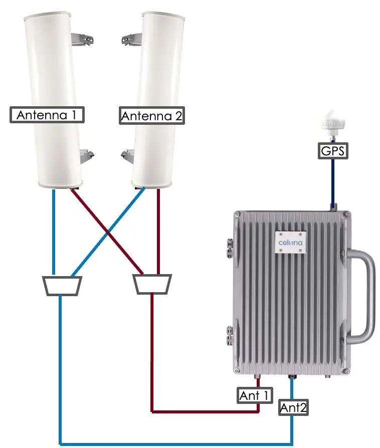
Each site differs in the type and number of components, coverage area, and requirements. Identify the mounting structure, the intended height, the antenna down-tilt, and any site-specific factors before you begin. AP 25 operates in single-carrier mode using ANT1 and ANT2.
Total output EIRP for AP25-48 is governed by FCC Part 96 - power is calculated and regulated automatically by Celona software. Choose antenna elements that support the channel of operation.
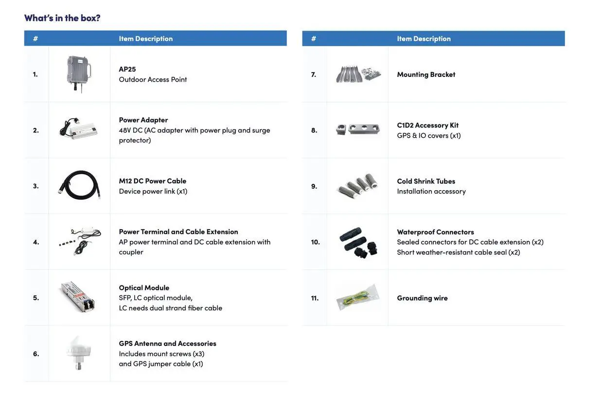
What's in the box
Interfaces
| Interface | Description |
|---|---|
| DCIN | Power supply: −48 VDC (−60 V to −42 V) |
| GPS | Port for optional external GPS antenna, N-female connector |
| ANT1 | Port for external RF antenna 1, N-female connector |
| ANT2 | Port for external RF antenna 2, N-female connector |
| SFP | Optical backhaul interface for the external transmission network |
| WAN | RJ-45 interface, used for data backhaul |
| STATUS | Single status LED |
LED status
| Colour | State | Meaning |
|---|---|---|
| Blue | Flashing | Software is initializing |
| Blue | Solid | AP25-48 is up and operational |
| Red | Steady | Hardware alarm |
| Off | - | No alarm |
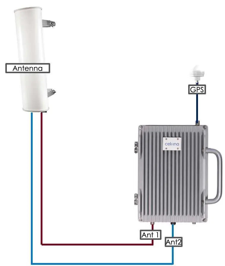
RF wiring diagrams
02
Location & environment
AP 25 can be installed on a pole or a wall. For the best signal coverage, place it in an unobstructed location. Beyond network planning, consider climate, hydrology, geology, earthquake risk, reliable power, and transport access.
Avoid
Extreme temperatures, harmful gases, unstable voltage, volatile vibration, loud noise, flames, explosives, or EMI (e.g. radar stations, substations). Avoid impounded water, soaking, leakage, or condensation. The AP is certified for Class I, Div. 2 HAZLOC installation.
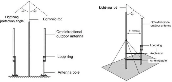
Grounding & lightning protection
The accessory kit includes a 14 AWG stranded copper ground wire (green/yellow) for reliable, low-resistance earthing. All joints must be corrosion-protected and mechanically secure.
03
Process overview
The installation proceeds in the following order. Each stage is detailed in its own section below.
- Weatherproof all connection points with cold shrink tubes
- Install the GPS antenna bracket
- Mount the AP on a pole or wall
- Connect cables - GPS, RF, power, and ground
- Fit the C1D2 accessory kit (hazardous-location sites only)
- Install the antenna feeder system
04
Weatherproofing
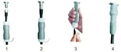
To protect connection points from weather, clean each point and fit cold shrink tubes before and during cabling.
-
1
Clean each connection point thoroughly before fitting the tube.
-
2
Insert the cable into the cold shrink tube.
-
3
Tighten the connector.
-
4
Push the cold shrink tube to the top joint and pull out the strip. Ensure the tube is tightly fitted to the connection.
05
Install GPS antenna
GPS works best with clear line of sight to the sky - at least 45° unobstructed. Avoid proximity to other transmitting/receiving devices, and install within 45° of the lightning rod.
The GPS antenna is pre-assembled in manufacturing. The only step is to fix the GPS mounting bracket to the AP 25 using the supplied M4×14 screws.
- Mount above the roofline with 180°+ clear sky; avoid ledges, ducts, and beams.
- Keep a 30-50 cm horizontal offset from antennas, poles, or large metal.
- Use mast/pole extensions to clear obstructions; mount rigidly with no tilt or vibration.
06
Install AP on pole or wall
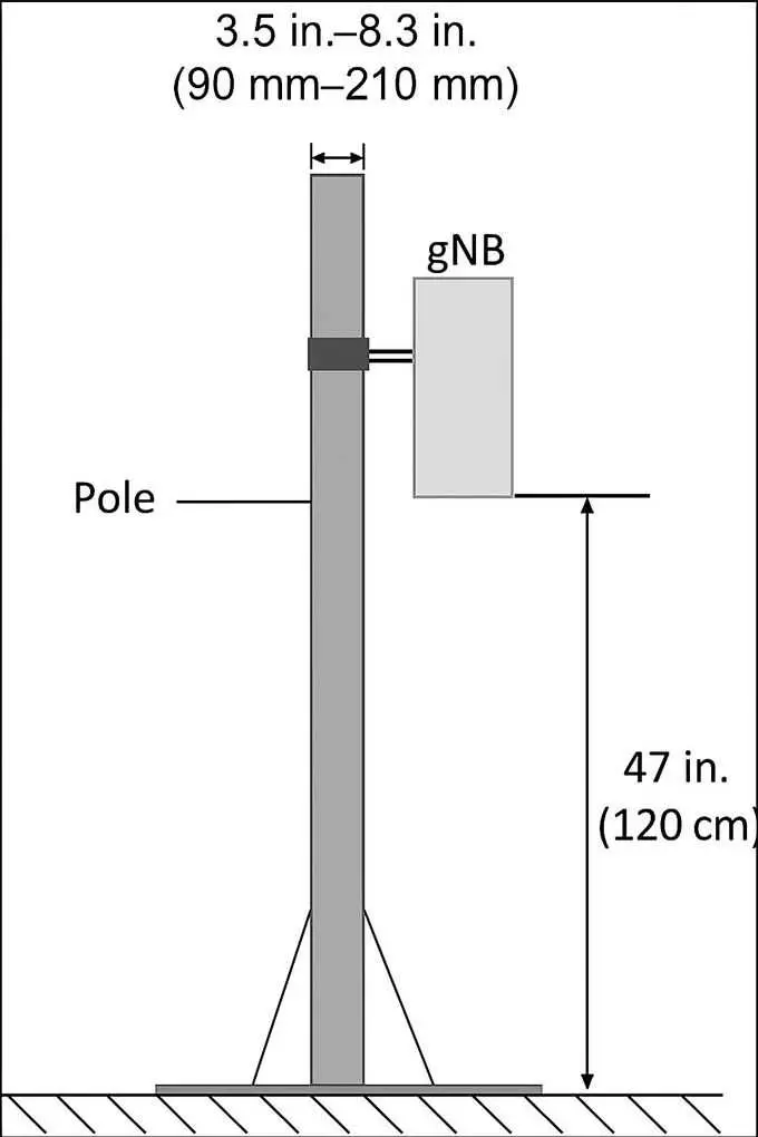
Pole mount
Pole diameter must be 3.5-8.3 in (90-200 mm). Mount the AP at least 47 in (120 cm) high. The mounting bracket ships pre-assembled in two parts: the bracket on the back of the device and the pole/wall bracket.
-
1
Identify the front and rear fixed frames, threaded rods, washers, and nuts. Insert the rods through the front frame and secure with washers and nuts; attach the rear frame to the opposite ends and tighten loosely to allow adjustment.
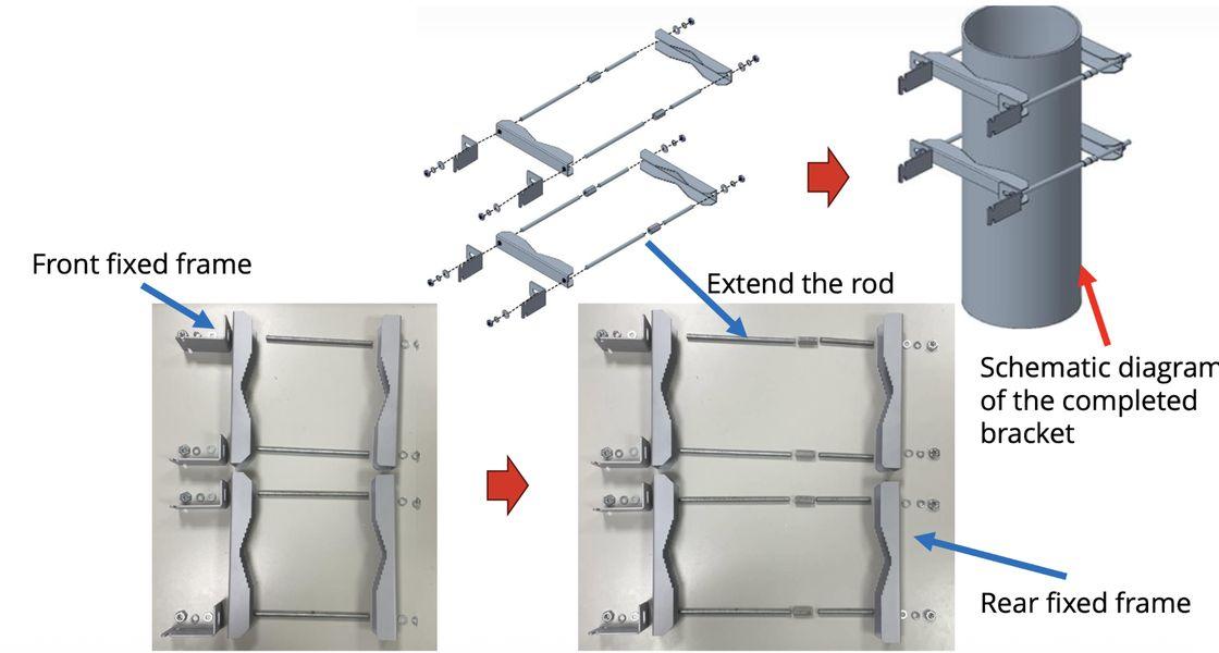
Front/rear frames and threaded rods
-
2
Align both frames, extend the rods evenly to match the pole diameter, then tighten all nuts securely.
-
3
Hold the AP 25 vertically and align the two pins on the AP bracket with the holes on the pole bracket. Push down until the hooks engage the slots.
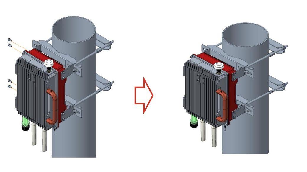
Engage hooks into the pole bracket
-
4
Tighten the bolt and screw on top of the AP 25 with a Phillips-head screwdriver. Once complete, proceed to connect cables.
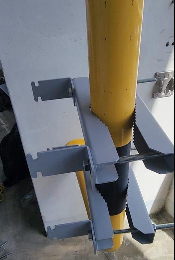
Completed bracket mounted on pole
Wall mount
The wall must bear at least four times the weight of the AP 25.
-
1
Assemble the wall-mount brackets on both sides of the access point with the provided screws and washers; ensure all brackets are securely fastened and aligned evenly.
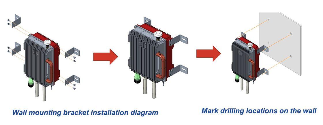
Wall-bracket assembly & drilling layout
-
2
Hold the access point against the wall in position and mark the drilling locations through the bracket holes for accurate placement.
-
3
Remove the access point, drill at the marked points, then proceed with final mounting.
07
Connect cables
General requirements
Respect minimum bend radii - antenna feeder 7/8″ ≥ 250 mm, 4/5″ ≥ 380 mm; power & ground ≥ 3× cable diameter; optical fiber ≥ 20× diameter. Do not intertwine or cross cables. Label every cable after laying.
GPS antenna cable
-
1
Insert the GPS jumper into a cold shrink tube and connect one end to the GPS antenna. Push the tube to the top joint and pull out the strip.
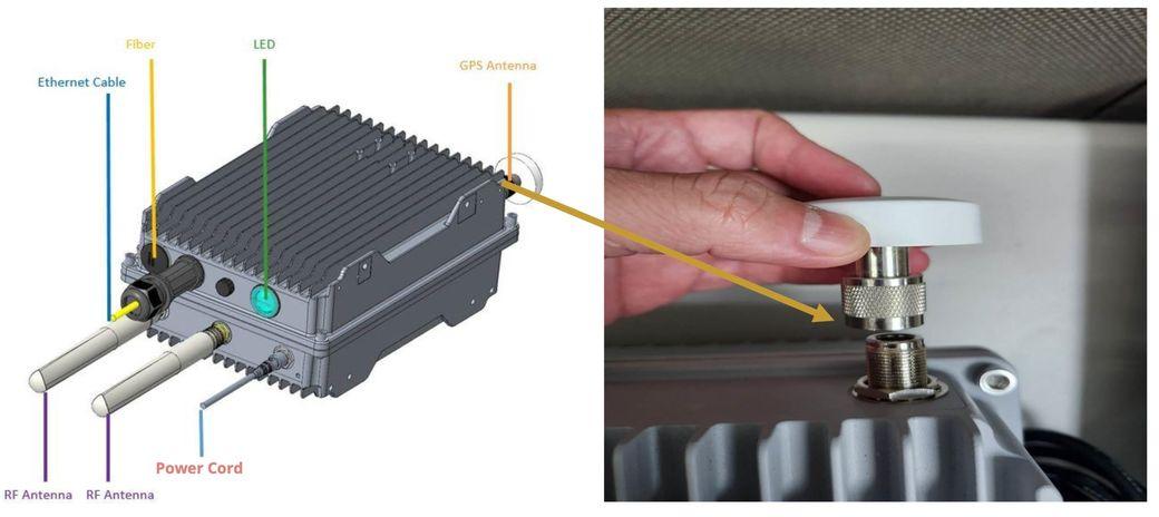
Connect the GPS jumper to the AP
-
2
Connect the other end to the GPS interface on the AP and weatherproof the connection.
Default 3-ft GPS cable
Use LMR-400 for outdoor, high-wind, and chemically exposed environments; extensions are supported up to 150 ft with matched N-male terminations.
RF cable
-
1
Open the dust caps on the ANT1 and ANT2 interfaces, then insert the RF cables into cold shrink tubes.
-
2
Connect one end of the RF cables to ANT1 and ANT2 and tighten with a wrench. Push the cold shrink tube to the top joint and pull out the strip.
-
3
Connect the other end to the external antennas and weatherproof the connection.
Keep the grounding cable separated from signal cables with sufficient distance to avoid interference.
Power connector
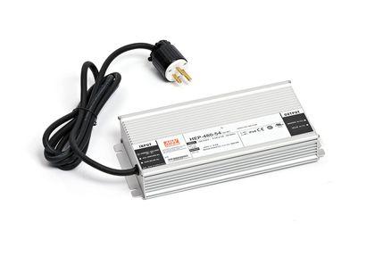
Power-cable length varies by site, so both ends of the adapter are bare terminals - make the cable to your site measurements and fit the power plug and terminal. Keep the run below 330 ft / 100 m.
-
1
Strip 0.47 in / 12 mm of insulation with a wire stripper for connecting to the connector.
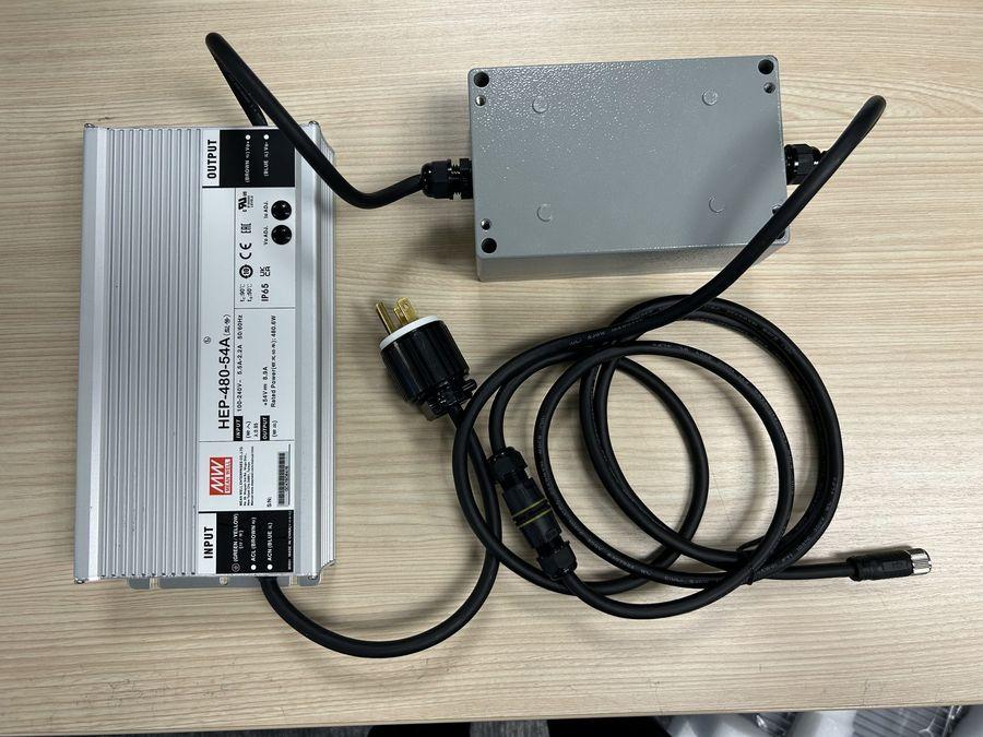
Power adapter with bare-terminal ends
-
2
Assemble the power plug on the input end - connect the live and ground wires to the labelled terminals and tighten the screws.
-
3
Assemble the power terminal on the output end - connect the live and neutral wires per the connector labels.
-
4
Route the power cable to the DCIN interface in the wiring cavity along the lint slot, then close the cavity cover with an M4 cross screwdriver.
If the outlet is outdoors, place the power adapter in a waterproof box.
Ground cable
The AP 25 has two grounding screws located on the bottom of the unit.
-
1
Prepare the grounding cable to the site measurements. Unscrew one grounding screw, connect one end of the ground cable, and fasten it again. Connect the other end to a proper grounding point.
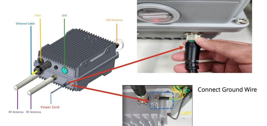
Connect the ground cable to the bottom screw
08
C1D2 accessory kit
Important
The AP25-48 C1D2 Accessory Kit (C-AP25-C1D2-KIT) is mandatory for Class I, Division 2 hazardous locations and must be ordered separately. The AP hardware is C1D2-ready, but the kit is not included with the AP25 package.
The kit includes a C1D2 metal cover for the power and antenna ports, a C1D2 metal cover for the GPS port, and a metal conduit connector and washer. The installer provides 1″ metal flexible conduit and fittings.
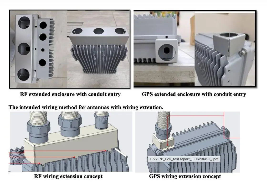
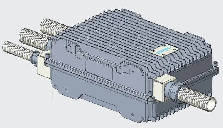
- Mount the AP25-48 securely inside the certified enclosure using the supplied bracket and screws.
- Route all cables through approved glands and flexible metal conduit; ensure threads are fully engaged and seals intact.
- Maintain proper bend radius and strain relief to avoid mechanical stress on the glands.
- The conduit must fully cover all exposed antenna and power cable within the C1D2 area.
- Reverse the antenna short-cable insert - the surge protector cannot be accommodated inside the metal conduit.
Approved glands and conduit prevent ignition hazards from gas or vapor exposure. Compliant with UL/IEC 60079-15 and ANSI/ISA 12.12.01.
09
Install antenna feeder system
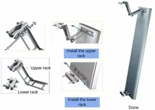
Two outdoor antenna types are supported: omni-directional and directional. Mount the antenna and feeder racks per the diagram, installing the upper and lower racks in sequence.